/*
========================================================================
Digital Code Lock With Keyboard Interfacing in AVR
Author : Gaurav Kumar Garg
garg.gaurav52@gmail.com
Version Release: 06-19-2013.1
GNU GPL Licence
In this project row are connected to first four pin of C Port
Coloum are connected to first four pin of D Port
========================================================================
*/
#include <avr/io.h>
#include <util/delay.h>
unsigned char ch1[4],ch2[4],i;
void delay(unsigned int ch)
{
_delay_ms(ch);
}
void key_init()
{
DDRC=0X0F; //Make port c as output
DDRD=0X00; //Make port D as input
DDRA=0XFF; // Just for testing purpose
}
void lcd_init()
{
DDRB=0xff; // make port b is an output port for display data on lcd
dis_cmd(0x02); // to initilize in 4 bit mode
dis_cmd(0x28);
dis_cmd(0x0c);
delay(250);
}
void lcd_cmd(unsigned char ch)
{
PORTB=ch;
PORTB|=(1<<PB0); // make EN=1
PORTB&=~(1<<PB1); //make r/w=0 for writing
PORTB&=~(1<<PB2); //make RS =0 for command
delay(250);
PORTB&=~(1<<PB0); // high to low pulse EN = 0
}
void lcd_data(unsigned char ch)
{
PORTB=ch;
PORTB|=(1<<PB0); // make EN=1
PORTB&=~(1<<PB1); //make r/w=0 for writing
PORTB|=(1<<PB2); //make RS =1 for data
delay(250);
PORTB&=~(1<<PB0); // high to low pulse EN = 0
}
void dis_cmd(unsigned char ch)
{
unsigned char value;
value=ch&0xf0;
lcd_cmd(value);
value=(ch<<4)&(0xf0);
lcd_cmd(value);
delay(20);
}
void dis_data(unsigned char ch)
{
unsigned char value;
value=ch&0xf0;
lcd_data(value);
value=(ch<<4)&(0xf0);
lcd_data(value);
delay(20);
}
void lcd_string(unsigned char ch[])
{
unsigned int i=0;
while (ch[i]!='\0')
{
dis_data(ch[i]);
i++;
// delay(20);
}
}
unsigned char a[4][4]={
'1', '2', '3', '4',
'5', '6', '7', '8',
'9', '0', 'A', 'B',
'C', 'D', 'E', 'F',
};
char take_value(void)
{
unsigned char rowloc,colloc,key;
// key_init();
// lcd_init();
// while (1)
{
unsigned int i=0;
do
{
PORTC&=0X00; // Ground all row
PORTD=0X0F;
colloc=(PIND & 0X0F);
}while (colloc!=0X0F); // check until all key are released
do
{
delay(20);
colloc=(PIND & 0X0F);
}while (colloc==0x0f); //wait for key press
// Now Checking for particular row
while (1)
{
PORTC=0X0E;
colloc=PIND & 0X0F;
if (colloc!=0x0f)
{
rowloc=0;
//dis_data('0');
break;
}
PORTC=0X0D;
colloc=PIND& 0X0F;
if (colloc!=0x0f)
{
rowloc=1;
//dis_data('1');
break;
}
PORTC=0X0B;
colloc=PIND & 0X0F;
if (colloc!=0x0f)
{
rowloc=2;
// dis_data('2');
break;
}
else
{
PORTC=0x07;
colloc=PIND & 0X0F;
rowloc=3;
//dis_data('3');
break;
}
}
//dis_data('rowloc');
//dis_data('1'); //for testing purpose
// Now Detect coloum pressed
if (colloc==0x0E)
key=a[rowloc][0];
else if (colloc==0x0D)
key=a[rowloc][1];
else if (colloc==0x0B)
key=a[rowloc][2];
else
key=a[rowloc][3];
// ch1[i]=key;
// dis_data(key);
}// end of first while(1) loop
// dis_data(key);
return key;
}// end of main loop
void main()
{
unsigned char key;
key_init();
lcd_init();
lcd_string("*Enter Password*");
dis_cmd(0xc0);
int flag=1;
for (i=0;i<4;i++)
{
// key=take_value();
ch1[i]=take_value();
key=ch1[i];
lcd_string("*");
// dis_data(key);
// dis_data();
// lcd_string(key);
}
dis_cmd (0x01);
dis_cmd (0x80);
lcd_string("Enter Again");
dis_cmd(0xC0);
for (i=0;i<4;i++)
{
ch2[i]=take_value();
lcd_string ("*");
}
for (i=0;i<4;i++)
{
if (ch1[i]!=ch2[i])
flag=0;
}
dis_cmd (0x01);
dis_cmd (0x80);
if (flag==0)
lcd_string("Wrong Password");
else
lcd_string("Lock Opening...");
if (flag!=0)
{
PORTA|=(1<<PA0); // For Glowing LED if Password enter is correct
}
}
========================================================================
Digital Code Lock With Keyboard Interfacing in AVR
Author : Gaurav Kumar Garg
garg.gaurav52@gmail.com
Version Release: 06-19-2013.1
GNU GPL Licence
In this project row are connected to first four pin of C Port
Coloum are connected to first four pin of D Port
========================================================================
*/
#include <avr/io.h>
#include <util/delay.h>
unsigned char ch1[4],ch2[4],i;
void delay(unsigned int ch)
{
_delay_ms(ch);
}
void key_init()
{
DDRC=0X0F; //Make port c as output
DDRD=0X00; //Make port D as input
DDRA=0XFF; // Just for testing purpose
}
void lcd_init()
{
DDRB=0xff; // make port b is an output port for display data on lcd
dis_cmd(0x02); // to initilize in 4 bit mode
dis_cmd(0x28);
dis_cmd(0x0c);
delay(250);
}
void lcd_cmd(unsigned char ch)
{
PORTB=ch;
PORTB|=(1<<PB0); // make EN=1
PORTB&=~(1<<PB1); //make r/w=0 for writing
PORTB&=~(1<<PB2); //make RS =0 for command
delay(250);
PORTB&=~(1<<PB0); // high to low pulse EN = 0
}
void lcd_data(unsigned char ch)
{
PORTB=ch;
PORTB|=(1<<PB0); // make EN=1
PORTB&=~(1<<PB1); //make r/w=0 for writing
PORTB|=(1<<PB2); //make RS =1 for data
delay(250);
PORTB&=~(1<<PB0); // high to low pulse EN = 0
}
void dis_cmd(unsigned char ch)
{
unsigned char value;
value=ch&0xf0;
lcd_cmd(value);
value=(ch<<4)&(0xf0);
lcd_cmd(value);
delay(20);
}
void dis_data(unsigned char ch)
{
unsigned char value;
value=ch&0xf0;
lcd_data(value);
value=(ch<<4)&(0xf0);
lcd_data(value);
delay(20);
}
void lcd_string(unsigned char ch[])
{
unsigned int i=0;
while (ch[i]!='\0')
{
dis_data(ch[i]);
i++;
// delay(20);
}
}
unsigned char a[4][4]={
'1', '2', '3', '4',
'5', '6', '7', '8',
'9', '0', 'A', 'B',
'C', 'D', 'E', 'F',
};
char take_value(void)
{
unsigned char rowloc,colloc,key;
// key_init();
// lcd_init();
// while (1)
{
unsigned int i=0;
do
{
PORTC&=0X00; // Ground all row
PORTD=0X0F;
colloc=(PIND & 0X0F);
}while (colloc!=0X0F); // check until all key are released
do
{
delay(20);
colloc=(PIND & 0X0F);
}while (colloc==0x0f); //wait for key press
// Now Checking for particular row
while (1)
{
PORTC=0X0E;
colloc=PIND & 0X0F;
if (colloc!=0x0f)
{
rowloc=0;
//dis_data('0');
break;
}
PORTC=0X0D;
colloc=PIND& 0X0F;
if (colloc!=0x0f)
{
rowloc=1;
//dis_data('1');
break;
}
PORTC=0X0B;
colloc=PIND & 0X0F;
if (colloc!=0x0f)
{
rowloc=2;
// dis_data('2');
break;
}
else
{
PORTC=0x07;
colloc=PIND & 0X0F;
rowloc=3;
//dis_data('3');
break;
}
}
//dis_data('rowloc');
//dis_data('1'); //for testing purpose
// Now Detect coloum pressed
if (colloc==0x0E)
key=a[rowloc][0];
else if (colloc==0x0D)
key=a[rowloc][1];
else if (colloc==0x0B)
key=a[rowloc][2];
else
key=a[rowloc][3];
// ch1[i]=key;
// dis_data(key);
}// end of first while(1) loop
// dis_data(key);
return key;
}// end of main loop
void main()
{
unsigned char key;
key_init();
lcd_init();
lcd_string("*Enter Password*");
dis_cmd(0xc0);
int flag=1;
for (i=0;i<4;i++)
{
// key=take_value();
ch1[i]=take_value();
key=ch1[i];
lcd_string("*");
// dis_data(key);
// dis_data();
// lcd_string(key);
}
dis_cmd (0x01);
dis_cmd (0x80);
lcd_string("Enter Again");
dis_cmd(0xC0);
for (i=0;i<4;i++)
{
ch2[i]=take_value();
lcd_string ("*");
}
for (i=0;i<4;i++)
{
if (ch1[i]!=ch2[i])
flag=0;
}
dis_cmd (0x01);
dis_cmd (0x80);
if (flag==0)
lcd_string("Wrong Password");
else
lcd_string("Lock Opening...");
if (flag!=0)
{
PORTA|=(1<<PA0); // For Glowing LED if Password enter is correct
}
}
 |
| Digital Code Lock ( It will ask you for entering password ) |
 |
| Verifying Password (It will ask to enter password again for verifying ) |
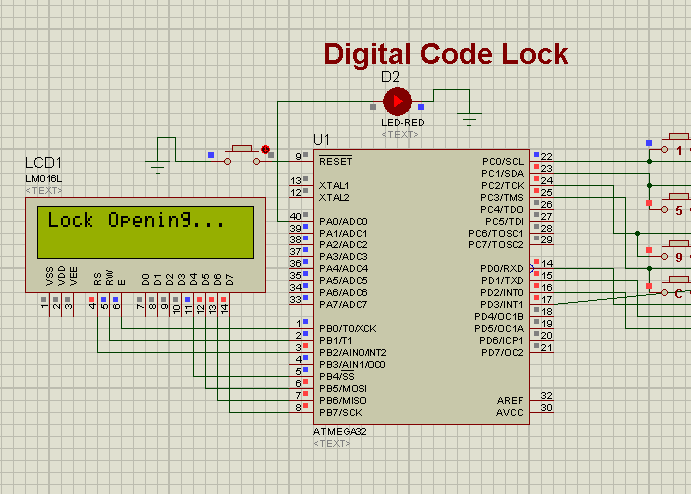 |
| If we enter correct Password then it will Switch Device ON (Hear RED LED is using as a Device which is connected to PORT PA0 ) |


